on top hat profile structure 0.5 mm with single sheathing of GKBI type H2 with a thickness of 12.5 mm
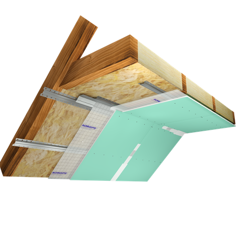
The above-mentioned parameters apply to a partition made of sheet metal profiles with a thickness of 0.5 mm.
 smart
smart
Provides a lightweight stable body with proven performance. The solution guarantees quality at an attractive price.


Value of materials per 1 m2 of attic lining
:Value of materials per 1 m2 of attic lining
: {get_calculation_per_meter} PLNTotal value of materials for the attic lining surface area
:Total value of materials for the attic lining surface area
: {get_total_calculation} PLNThe above material consumption standards are just estimates and do not include waste resulting from material installation. The calculation does not constitute a commercial offer within the meaning of Article 66 § 1 of the Civil Code.
* In order to calculate the wall construction cost, enter material unit prices.
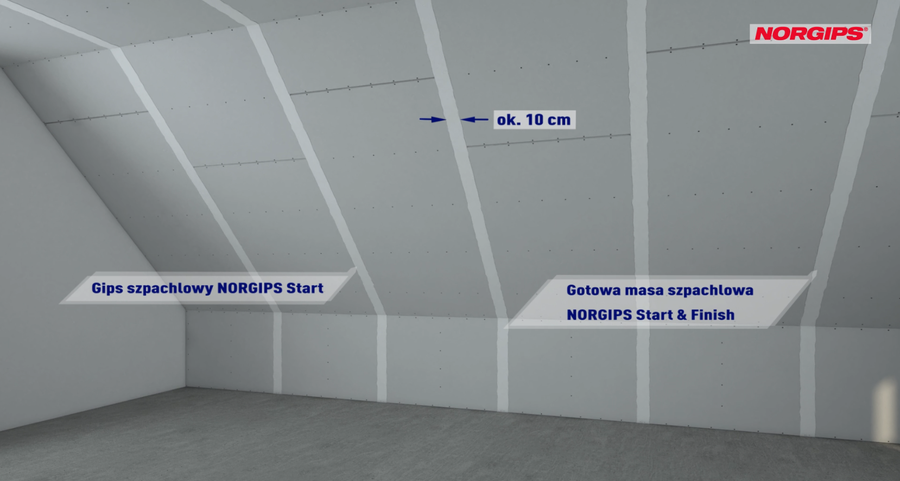
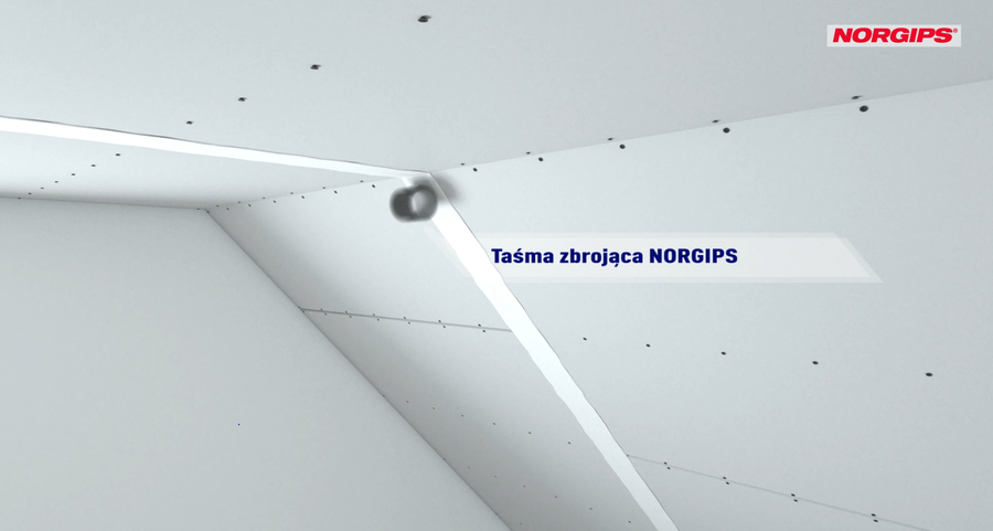
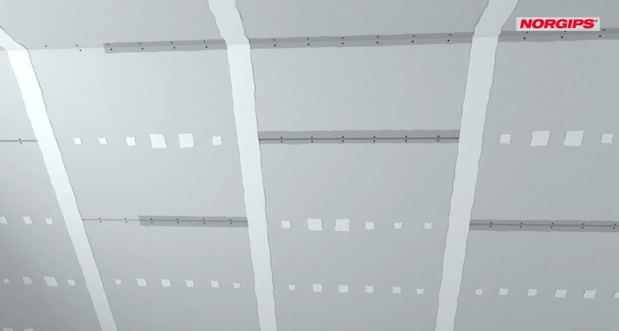
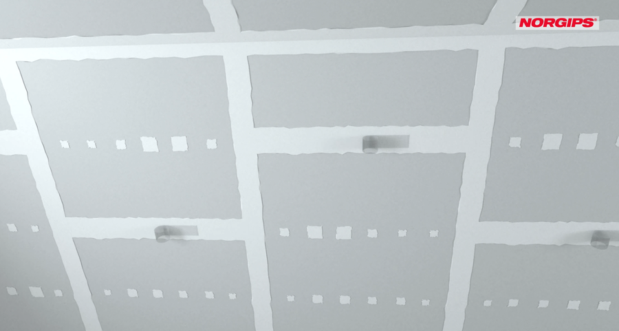
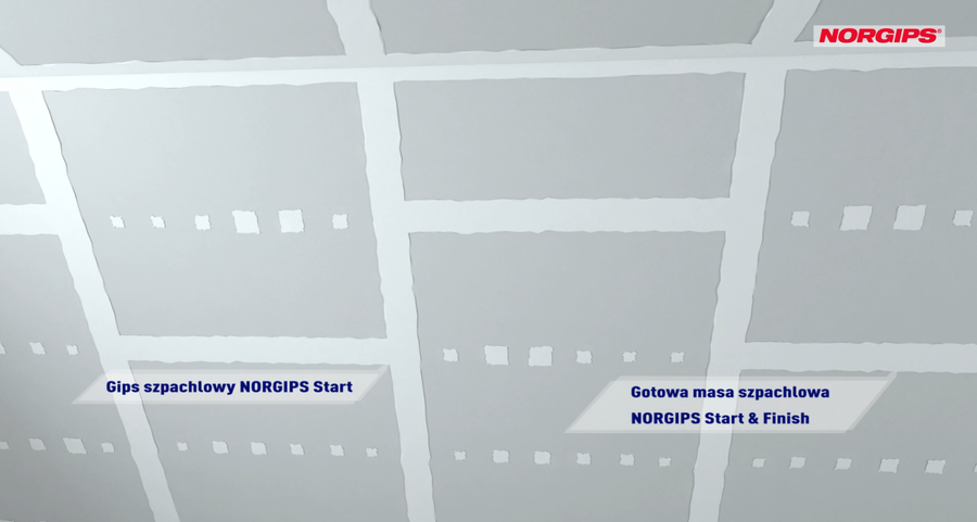
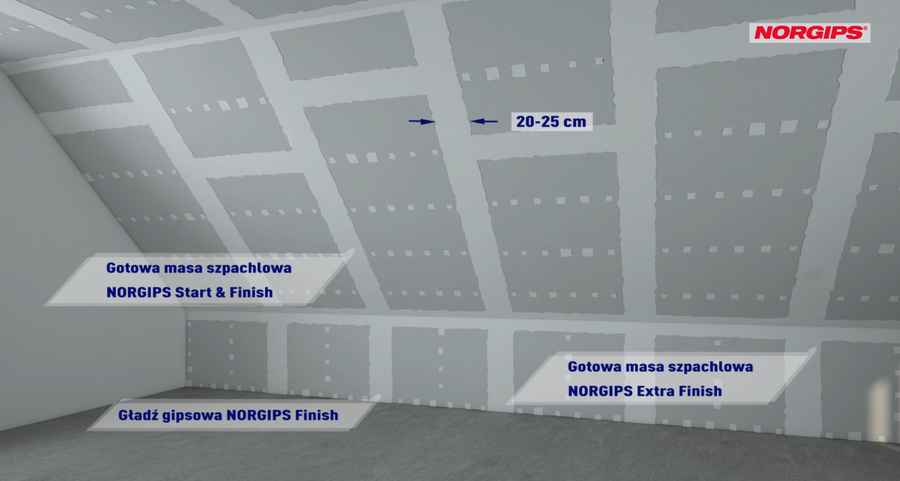
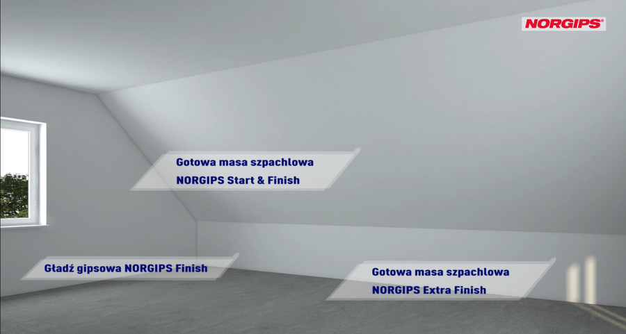
Q1 - Double filling of plasterboard joints and connections with a structural joint filler (Norgips Start & Finish or Norgips Star), sealing a reinforcing tape, covering visible fasteners with a joint filler
Q2 - Includes the Q1 scope plus filling plasterboard joints with a finish joint filler (Norgips Extra Finish, Norgips Start & Finish or Norgips Finish) until a smooth transition of a joint into a plasterboard surface is achieved
Q3 - Includes the Q2 scope plus filling the entire partition element (joints and cardboard) with an approx. 1 mm thick layer of finish joint filler (Norgips Extra Finish, Norgips Start & Finish or Norgips Finish) to level the surface, close all pores and consolidate absorptivity of filled surfaces
VIDEO tutorials
Find out how to properly install plasterboard in a loft, build a partition wall, suspended ceiling or a dry screed. Check out our VIDEO tutorials, as well as product tests and expert recommendations.
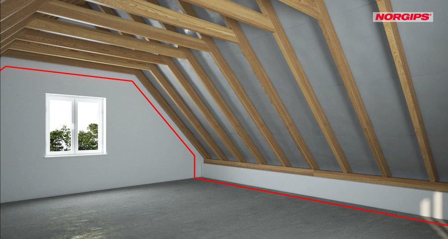
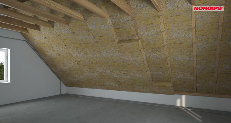
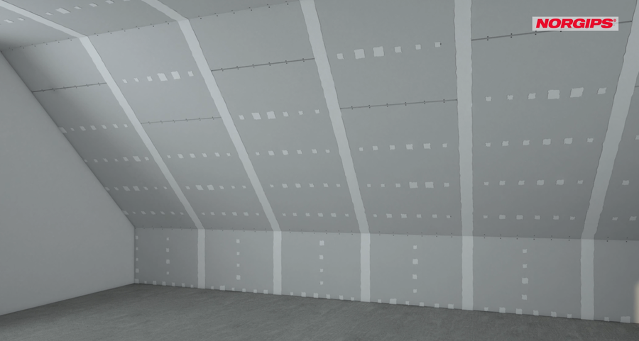
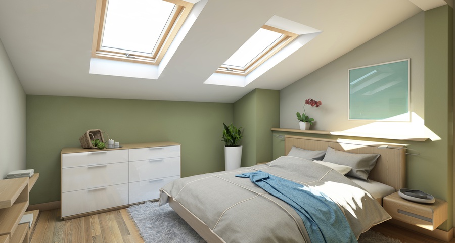
How do you make an attic properly?
By carrying out the attic lining according to the following tips, we will avoid unpleasant consequences in the future. The benefits of a properly constructed lining include: high thermal insulation to reduce heating costs in winter and cooling costs in summer, better acoustic insulation from outside noises, fire safety, high aesthetics of the encased surfaces (no cracks).
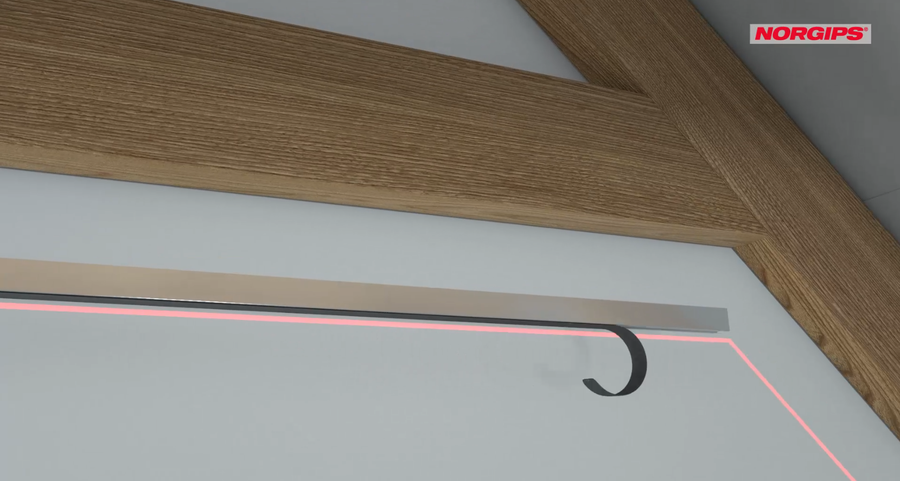
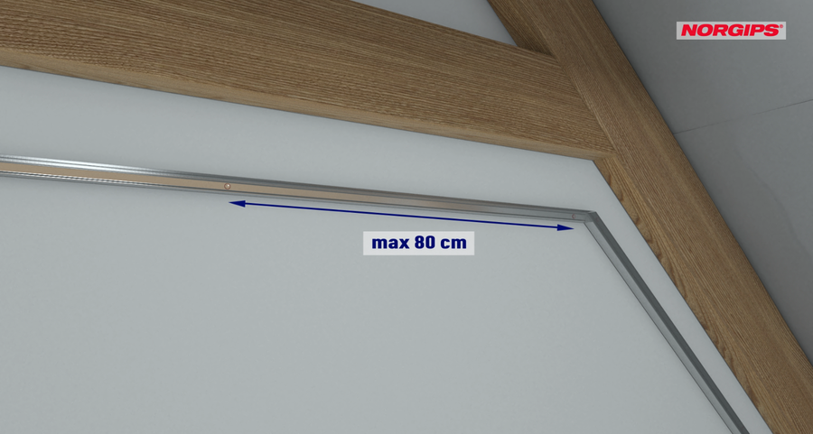
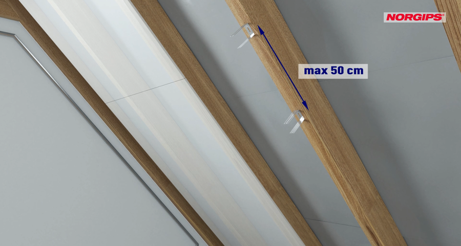
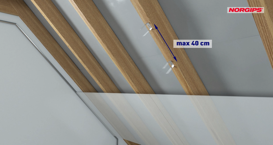
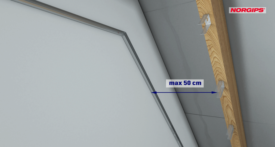
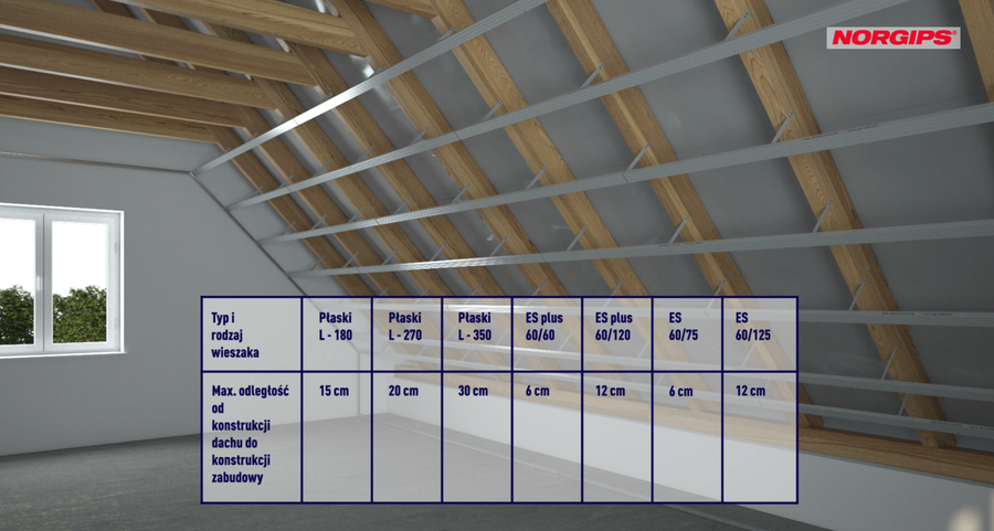
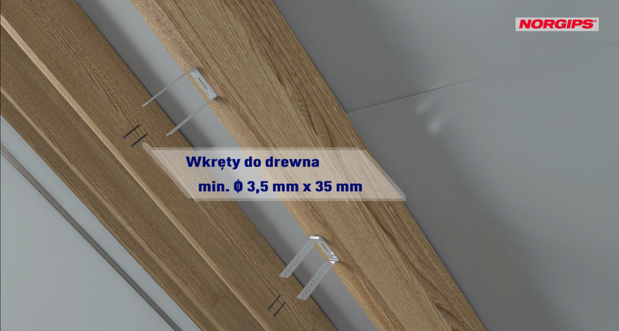
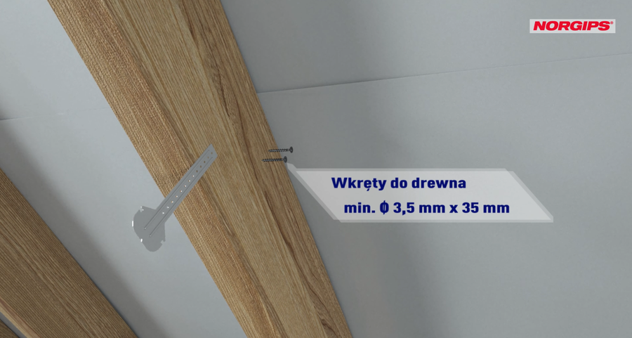
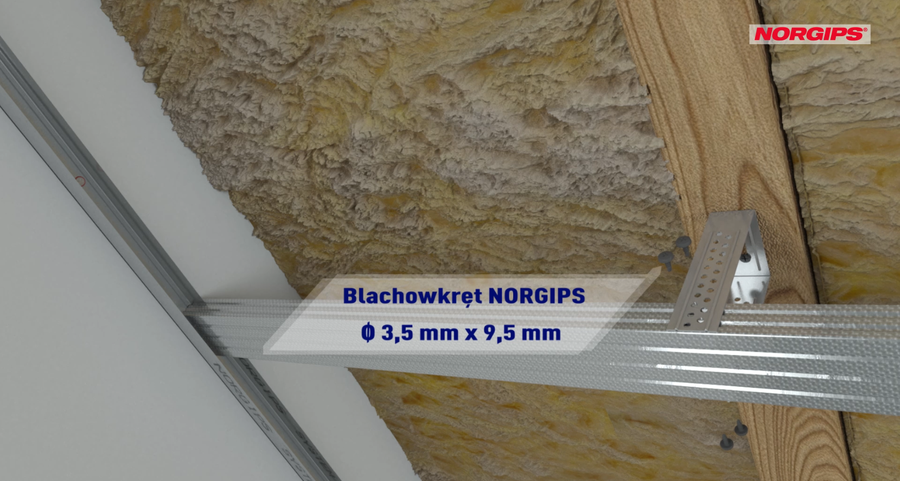
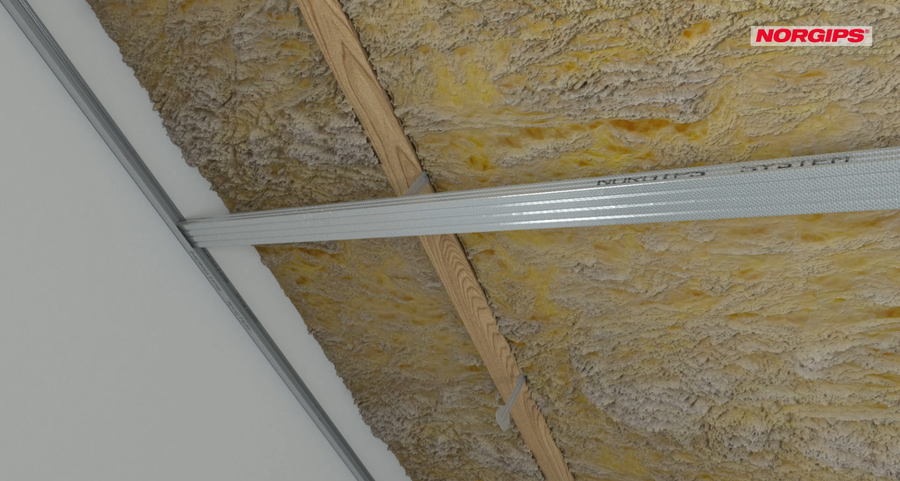
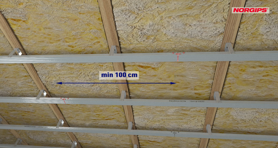
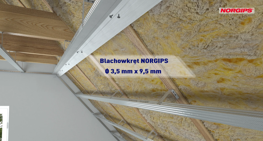
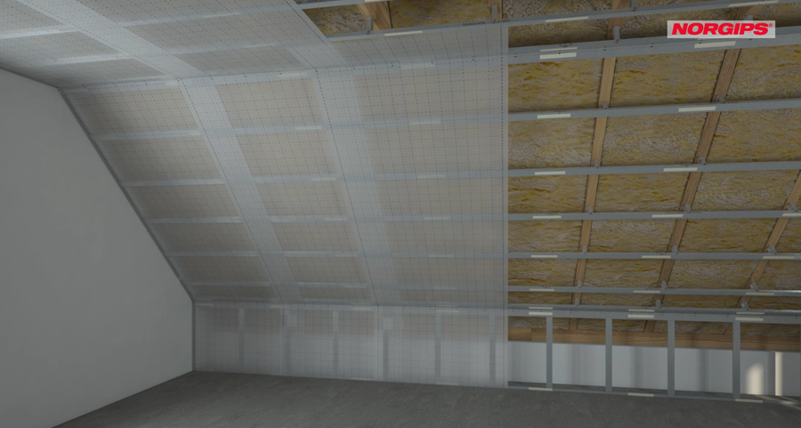
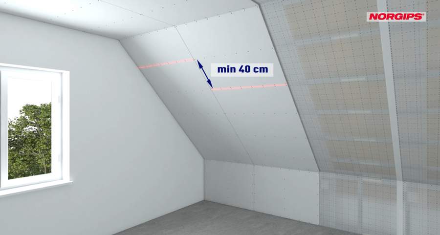
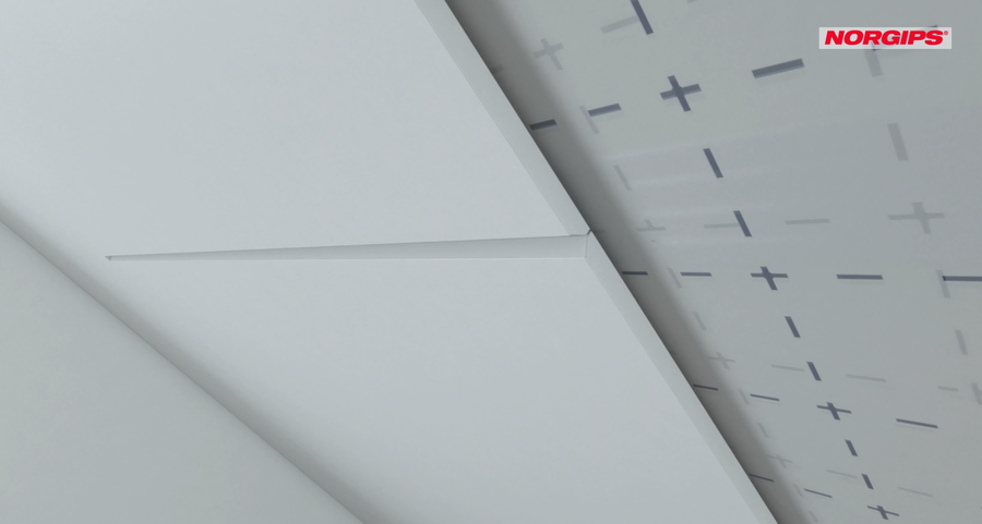
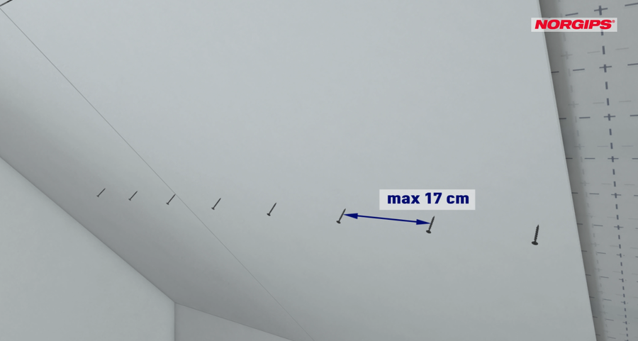
Below, we present the stages of attic lining in the form of described assembly steps and an animation showing how to do it correctly.
 New
New
 New
New
How to make a partition wall correctly? What products should be used in loft? How much does the plasterboard weigh? Our technical advisors can answer these and your other questions.
A selection of downloads and material consumption calculations from our website can be included in the document folder.
Click'To folder' on any document or calculation.
With the document folder you can easily prepare documentation for your investment including:


